Universal Step-Start System
Step-Start Systems and Universal Step Start Board
W8JI 12/21/2021
Amplifiers and power supplies can have very large initial contact closure currents. This starting current, also called “inrush”, primarily damages line switches and powerline relays or contactors. Severe inrush can also false-trip line breakers or open powerline fuses. Otherwise, inrush is generally harmless to typical components used in Amateur Radio amplifiers. In almost all amateur radio systems inrush will not reduce tube life, transformer life, rectifier life, or filter capacitor life. Inrush can create annoying cabinet or chassis “thuds” when an amplifier or transmitter is powered up, especially with gapped cores and steel cabinets.
There are two main causes of power switch and power relay contact damage, or false tripping of magnetic breakers or fast fuses; transformer residual magnetism and filter capacitor charging currents.
Residual magnetism parks the transformer out in random places on the B-H magnetic curve. If power line contact closure happens to hit wrong in relationship to the place the transformer parked on shut down, even if the switch starts from a zero crossing, the first fractional-cycle transformer primary impedance can be close to just wiring and winding resistance. When this happens, transformer primary dc path resistance alone limits transformer primary impedance. Extreme residual magnetism inrush cases are somewhat common in large closed-core transformers such as toroidal and Hypersil style transformers. This effect occurs with or without secondary loading.
Filter capacitor charge current is spread over the first few cycles. This current is limited by capacitor ESR, secondary system equivalent resistances, transformer flux leakage, and the total joules absorbed and stored in the capacitor system. Transformer primary system resistance aids in limiting this longer-duration current. Switching supplies also have inrush, primarily from energy storage capacitor charging currents.
Regardless of cause, the bulk of switch or relay contact damage occurs during the first few milliseconds while power switch or relay contacts are bouncing or settling.
Properly designed step-starts, more recently called “soft starts”, can be an effective solution to false breaker trips or fuse openings, as well as reducing switch and relay contact damage. Proper step-starts reduce starting current enough to prevent false breaker or fuse opening, limiting closure currents to reasonable levels during relay contact and switch bounce periods.
I include step-starts or “soft-starts” in designs only as necessary, the need primarily determined by the transformer style or other inrush determinants. It is important to mention that, to this date, there have never been documented tube life changes in amateur radio power level amplifiers through addition of or lack of a step-start. Step-starts or soft-starts primarily improve switch and contactor life, as well as reducing annoying false breaker openings or fuse fatigue. Step-starts also reduce or eliminate unimportant but annoying starting noises, such as cabinet “thuds”. Don’t count on them magically making a transformer or tube last years longer.
How Soft Starts and Step Starts Work
Step start systems insert a series resistance in the primary power source path. This start resistance can be inserted in either power line lead or in both supply line leads. Maximum possible inrush is found with Ohm’s law, E/R = I with E being the peak supply voltage and R being the total effective start resistance.
This start resistance is removed three ways:
1.) By a fixed time-delay system
2.) At a targeted primary winding voltage
3.) At a targeted secondary winding voltage
Each method above has advantages and disadvantages.
Systems In General
All systems require a high overload capable start resistor. Without protection, the start resistor may go incandescent or melt during prolonged fault states. The start resistor should be fused with a fuse that opens before major damage. The resistor, fused or not, should be kept clear of all easily damaged objects such as wiring harnesses or circuit boards. Fusing is an imperfect art, there will always be a balance between resistor fuse life and resistor damage, but some protection is better than a guaranteed melt-down.
Timer Based Systems Timer-based systems close the step-start (sometimes called a “soft-start”) at a preordained time regardless of inrush or starting load current. Time based systems always add some unnecessary start delay to ensure they do not close prematurely. Time based systems also will close into a dead short unless something detects the short and disables the timer. These systems will commonly start even if the inrush is not handled, such as when the start resistor has failed. The operator may think the inrush is working when it has failed.
Voltage Triggered Systems The simplest and most common systems are voltage triggered systems. Voltage triggered systems start at a predetermined trigger voltage range. This is my favorite system, because it is the most sensible system.
The instant a power supply starts, initial impedance across the power line is quite low. This is, of course, the cause of inrush. By adding resistance in series with the powerline, inrush current is limited. Voltage dropped across the inrush start resistor prevents activation of a shorting relay until equipment load impedance is well past the point of inrush. When supply impedance rises to safe values, trigger voltage becomes high enough to close a start-resistor shorting relay. This system always insures the fastest smoothest start without excessive inrush. Time delay automatically adjusts itself to the time necessary to prevent excessive current. This time will always be well beyond contact bounce periods.
As with the timer system, limiting resistors can be damaged by a power supply defect, but if the start resistor fails voltage triggered systems will not start. There is little chance of starting hard into a shorted load, or thinking the system is working when it is not working.
W8JI / CTR Engineering Step-start Board
My step-start design uses a commonly available heavy-duty high-current cube relay. The relay is specifically intended for powerline switching applications. More important, the relay uses a very common hole pattern and is readily available in 5 to 110-volt coil voltages. My board readily fits a wide range of applications. By repositioning two plug-in shunts, starting resistances of 11, 22, and 44 ohms are selected.
As determined by relay coil and board component population, trigger voltages of 5, 12, 24, 48, and 110 Vdc and 6, 12, 24, 48, and 120 Vac are available. Additionally, two 2-watt series-connected resistors allowed trigger threshold customizing to other trigger voltages.
This board accepts European style wire terminated or removable plug blocks. Terminals can also be eliminated and connections directly soldered to the board.
My board requires minimal changes in existing wiring, requiring only two small low-current trigger wires and interrupting of only one high current power line wire. This makes installation simple, fast, and clean-appearing. This board requires 1-1/2 inches or less vertical space and about 3 inches of length and width.
Additionally, we include a drill template and suitable hardware. All you need are common hand tools.
Minimal cost and complexity dc triggered board, UNSS12Vdc:
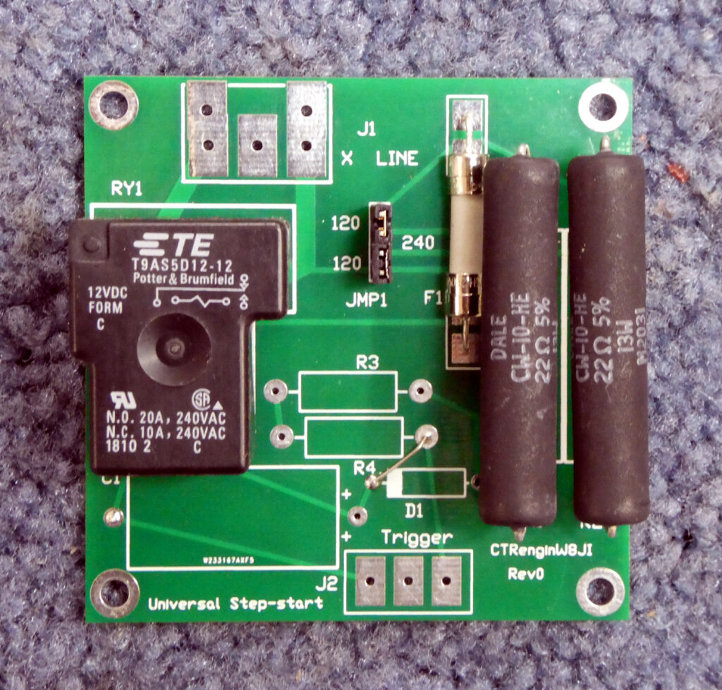
Universal Step Start configured for 12Vdc systems.
Basic board cost $35.00
Parts ORDERS or parts questions go to orders@ctrengineeringinc.com
Universal Step Start fully optioned and configured for 120Vac primary operation:
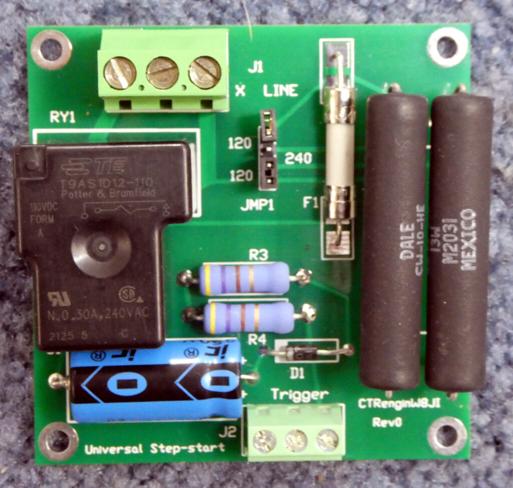
UNSSD120AC fully loaded 120Vac primary trigger.
Parts ORDERS or parts questions go to orders@ctrengineeringinc.com
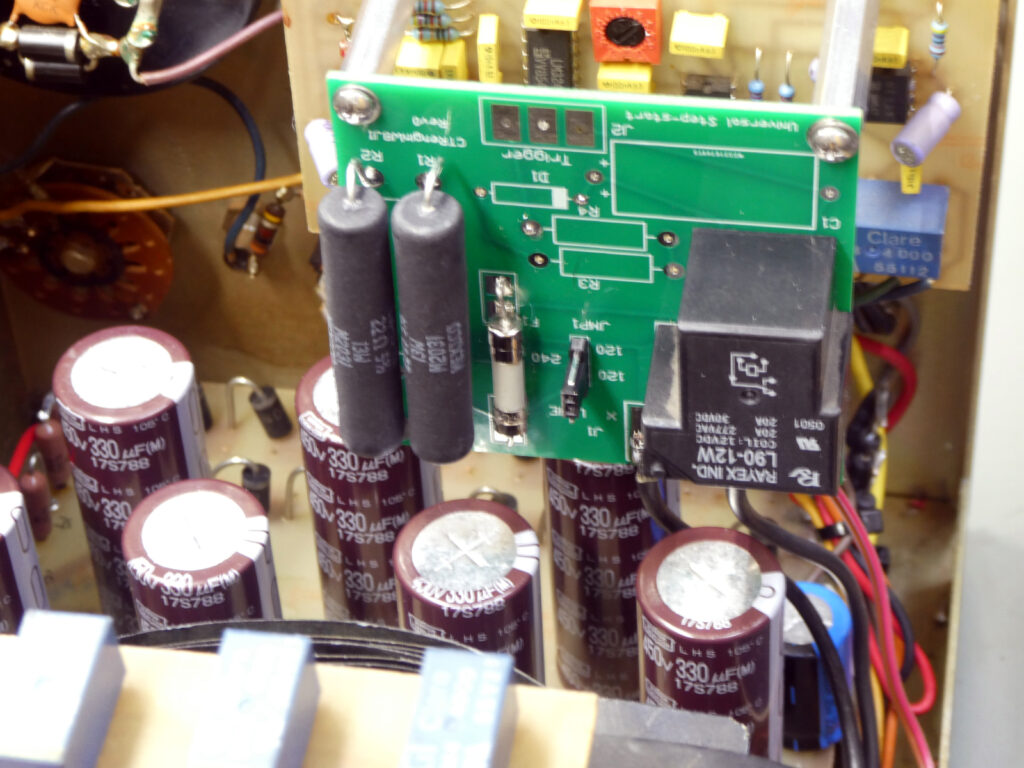
Example of a Universal Step-Start 12Vdc unit installed in LK500Z amplifier
Original unit had complex wiring, no fusing, and was glued in place:
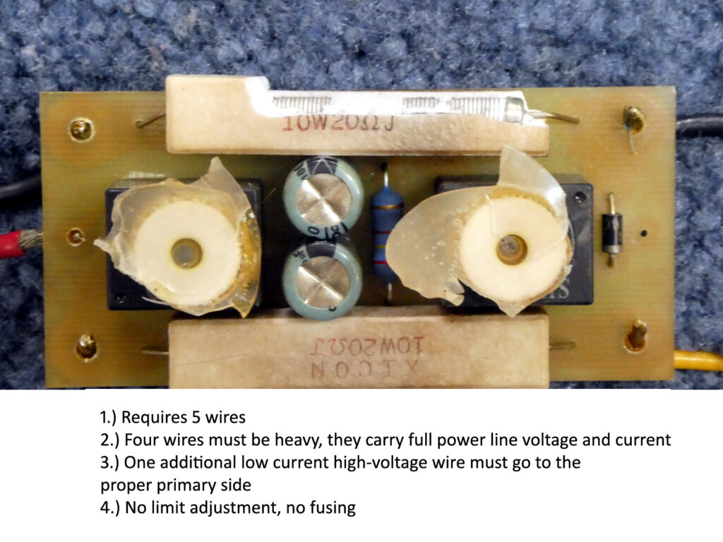
Replacement Universal Step Start activates from 12Vdc bus. Requires only two short small wires for trigger and interrupting of only one 240Vac lead! This makes a clean simple installation:
UNSS12dc installation Amp Supply Amplifier