TOF Installation AL80B
Most amplifiers require a unique TOF module. The wire colors and resistor values are different. Be sure you have the correct TOF module for your amplifier.
If you have the TOF with OL relay, you must alter standby switch wires.
LED Warning Indicator
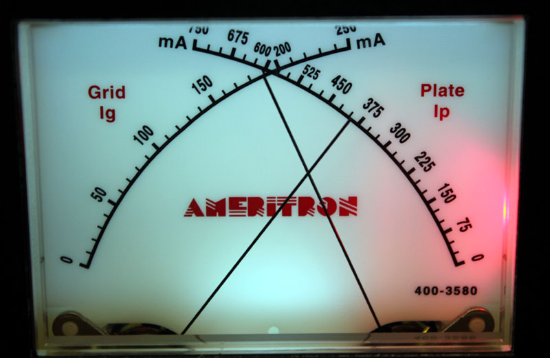
The LED warns by illuminating when exceeding the typical maximum peak grid current for proper linear amplification. R6 on the TOF board sets the illumination point. 4700 ohms is approximately 190 mA, but this varies slightly with component tolerances. (The grid meter is not perfectly accurate, and other components have tolerances.) If you slightly open the LOAD control clockwise and the LED does not go back to occasional sharp quick flashes, or does not stay completely off, the amplifier is being overdriven. Reduce the drive power until the LED just flashes occasionally, or stays completely off.
The warning LED may occasionally flash on voice peaks from radio power overshoot. This is generally not harmful or disruptive to others. If the LED illuminates longer than very brief flashes or blinks, or stays on with every word, the amplifier is being overdriven or is mistuned. The exact level where flashing occurs varies with tube.
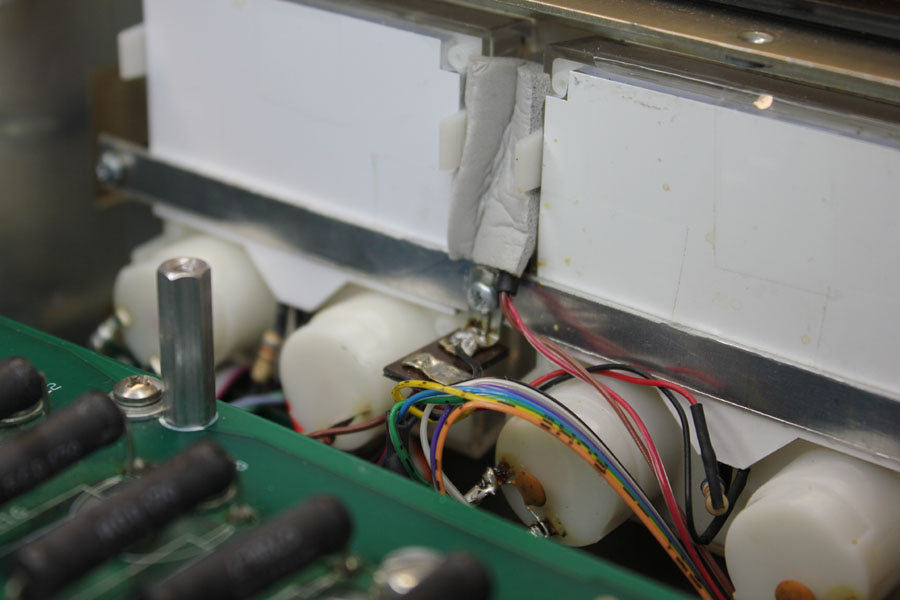
The LED can be mounted between the panel meters. The flash is much more noticeable than this photo.
Installation
| Tools required:#1 and #2 Phillips screwdrivers
Soldering equipment with small rosin flux solder, preferably WRAP2 rating but any electronics solder will work Included in kit: TOF1 with precut wires two small cable ties Heat shrink
|
Remove the power plug from the outlet, and after making sure the HV meter has reached zero, remove the cover.
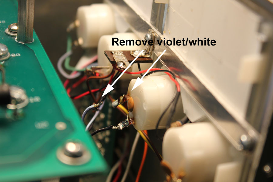 ‘
‘
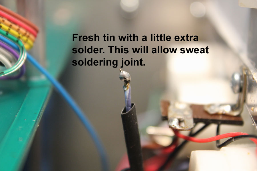
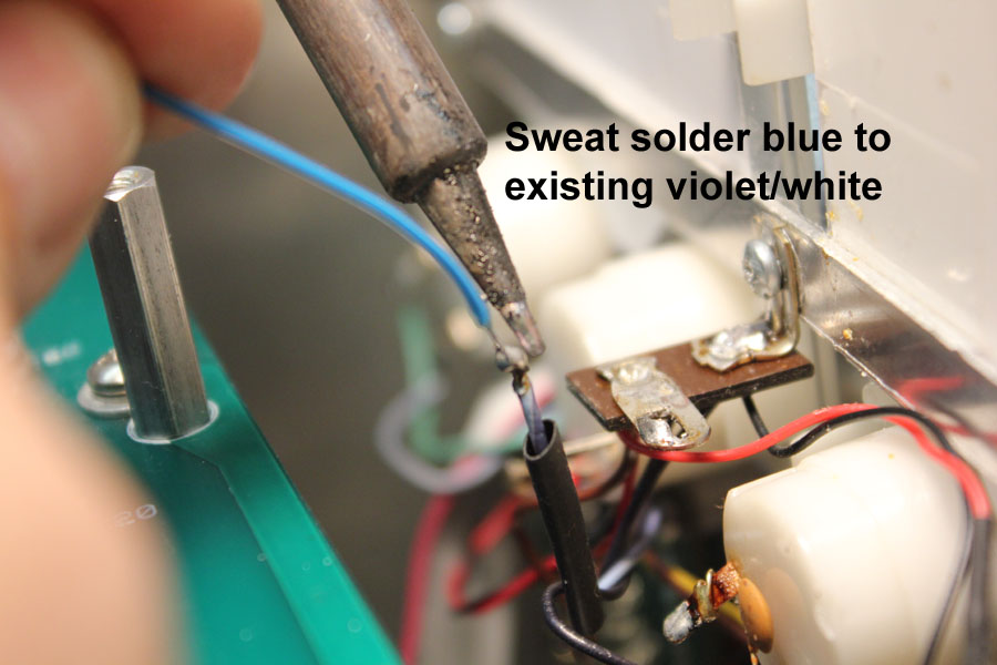
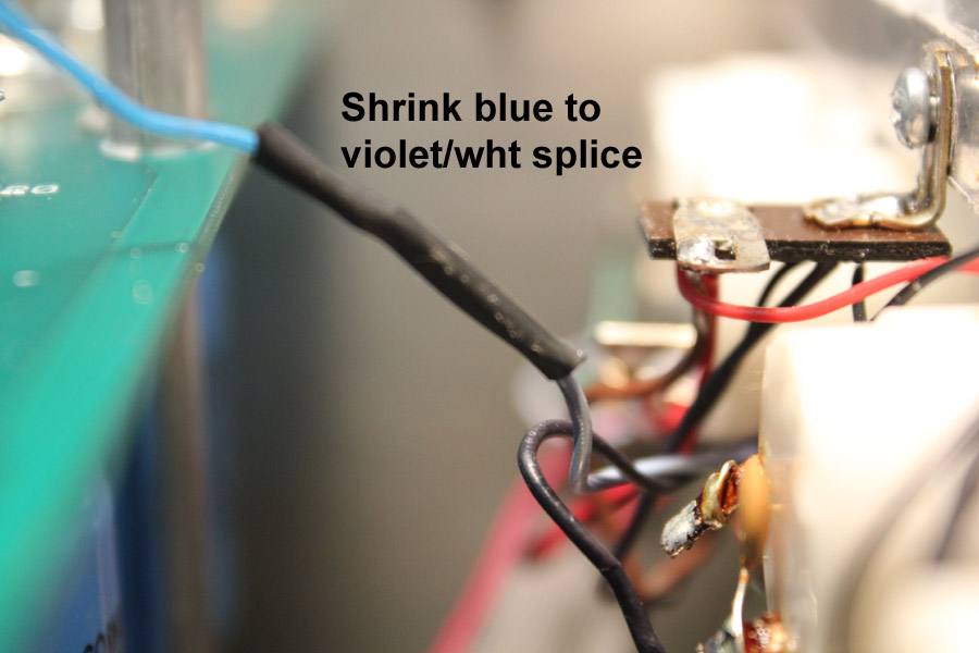
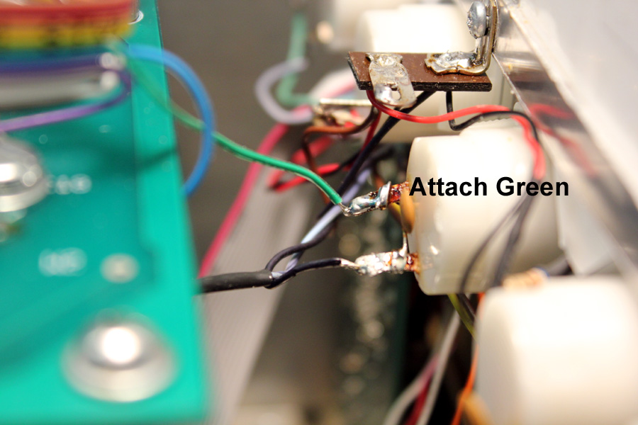
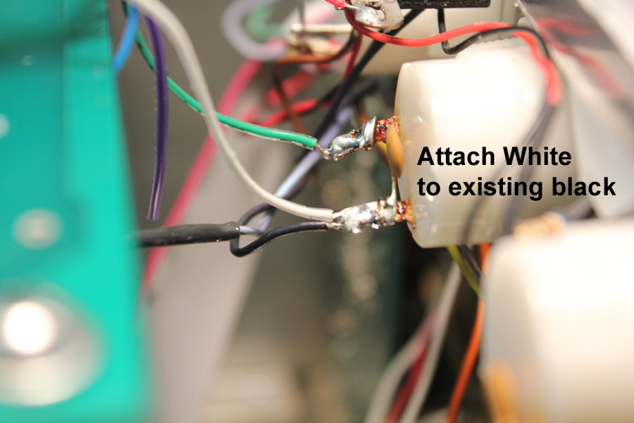
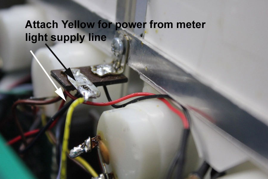
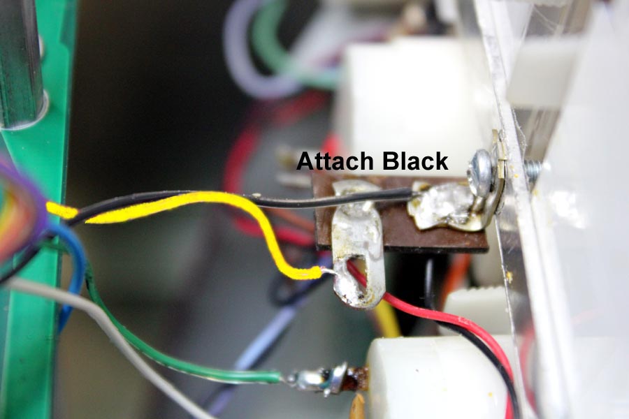
Next two steps for TOF with overload relay only!!
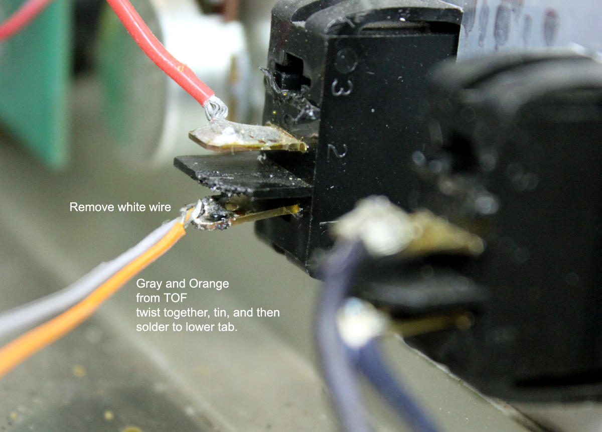
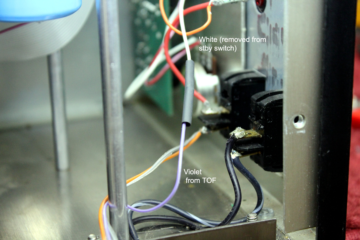
On all units continue
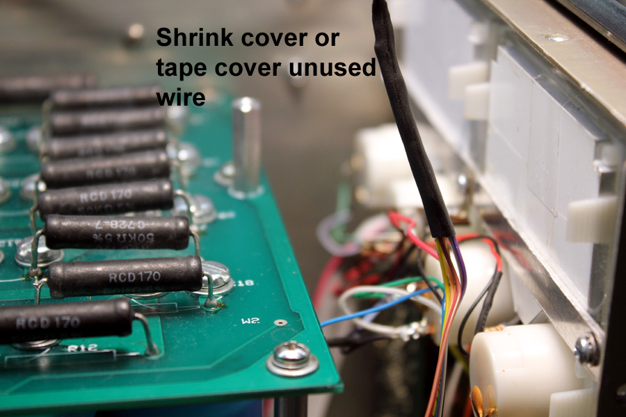
Mount LED
Operation notes:
The LED should light solidly at 200mA. This varies with tube and component tolerances. This is the grid current point where splatter rapidly gets worse. You must either reduce drive power, or increase loading setting. Do not push the amplifier to maximum possible RF output power, leave a few hundred watts headroom.
The overload disconnect trips off at 25% more current, approximately. This disconnect is to prevent damage, not splatter. It is reset by switching the amplifier to standby, and then back on.
